Cylinders and Porting
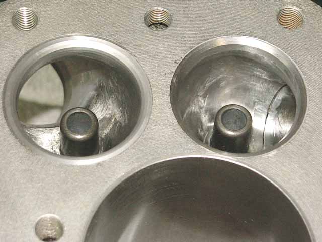
Here is a Chief cylinder that is mildly ported, sleeved, new guides, and has a nice 3 angle valve job.
Indian cylinders, whether Chief, or Scouts have pretty nasty intake, and exhaust ports. Now, combine this with all the very poor valve jobs done to cylinders along the way, and you have very poor breathing. I have found that there isn't alot of exotic porting that is needed. The ports are already pretty large, and sometimes too large. They just need cleaning up. If you feel inside a port just under the valve seats, you will find all kinds of rough edges. It is best to do porting when the valve guides are removed. Then you can get a skinny mandrel, and some tapered 80 grit cone shaped porting barrels, and get with it. Stay away from the valve seats, and just smooth everything. It takes me about (2) hours to make all (4) ports look very nice. Just clean, and smooth all the surfaces. For the valve job, I use hand valve seat cutting tools from "Nuway". You can go to "Goodson" for all your valve job tools. They sell the valve guide mandrels, and "Nuway" cutting heads. It's an investment that is well worth it if you want to maintain your own valve jobs. You would be surprised how expensive it can be to pay some machine shop to do a crappy job for you. Most machine shops just don't give the Indians the respect they deserve. A proper valve job has the outer-most edge of the valve head contacting the seat, and the width of the intake seat-cut needs to be 1/16" wide as measured from the outermost edge of the valve head, while the exhaust valve head seat width is 3/32" wide from the outer-most edge of the valve. This can be seen when the valve, and seat are lapped-in. To control these widths, you use a series of "Nuway" cutters, where you very carefully cut a little of the 35 degree, so it just extends outward, and inwards of the desired seat contact pattern on the valve head. Then you use a 15 degree "Nuway" cutter to knock off the edge of the 35 degree cut leaving the outer-most portion of the 35 degree cut at the outermost edge of the valve head. Then you use a 60 degree "Nuway" cutter to open up the 35 degree cut to the seat widths mentioned above. It is so very important to take your time, and go back, and forth with these cutters, so you don't go too far. Remember, you can take metal away, but you can't put it back! After you are done cutting the seats, they need to be lapped in for a smooth finish with 600 grit lapping compound. My so-called ex-machinest was charging me a fortune for inferior valve jobs, and after I spent about $500.00 for the "Nuway" cutters, and mandrels. I am now doing very fine valve jobs. Plus, I don't have to wait 3 months to get my cylinders back!
When the valve seats have been butchered by bad machinists, they need to have hard seats installed, and a new valve job done. Unfortunately, if a Chief, or Scout intake seat needs replacing, it will also require a cylinder sleeve installed. This is also the fix for cylinders that have a crack between the cylinder wall, and the intake port. It can be very expensive, but that's the way it is! You need to get valve seats that are slightly less than .250" thick, with an ID that is a bit less than .250 smaller than the valve head OD, so there is enough meat to port out to match the ports. The new seat OD should be 1/8" bigger than the valve head OD, so there is 1/16" of seat over-hanging the outside of the valve head. Do not cut the cylinder too deep for the new seat. It needs a little shelf to support the seat, that won't break away. Scout seats need to be set about .210" deep! After an intake seat has been installed, the new seat will be overhanging into the cylinder, and now you will have to have the cylinder sleeved. The bore job for the sleeve will cut away the edge of the intake seat, and the new sleeve will have the edge of the seat captured in place.
Sleeves are OK if they are installed correctly. I prefer the L.A. Sleeve "Ductile Iron" sleeves, which are about twice as expensive, but also about twice as hard! They last much longer, and possibly add more strength to a sleeved cylinder. A cylinder needs to be bored, and honed to a fine finish with an interferance fit of between .0015"-.002", and the cylinder heated in an oven at 300 degrees F., while the sleeve is frozen. They need to be quickly pressed together in a press using a block of hard wood, or aluminum plate to drive in the sleeve. You can use a soft mallet at first, and finish with the press. Do not use any locktite, or lubes. Do it dry, and quickly! Make sure there is a champfer in the cylinder that has no sharp edge that will cut the edge of the sleeve! Set the cylinder upside down on a flat surface, and press the sleeve down untill it bottoms on this surface flush with the cylinder deck. Then bore, and hone the sleeve for the final fit, and do your porting, and valve job. Take some 100 grit sand papaer, and smooth the inner edge of the sleeve at both ends. This helps the rings go in easier, and the sharp edge won't scratch the piston skirt as the piston goes downward.
Honing: Honing is a tricky business. The cross-hatch is there to give the oil something to hang on to. The honing stones will tear the metal as they leave the cross-hatch pattern, so a "Plateau" finish is done to knock off the torn edges. This will leave less debris in the oil during break-in, and accelerate the break-in process. It is a good idea to use a 10-40wt. oil for break-in for the first 50 miles, then replace it with 20-50wt for the next 500 easy miles, then replace it with straight 50 wt. oil. To get the right "Plateau" finish, you first bore the cylinder to within .002" of the finish size. Then hone with a coarse 150 grit stone to clean-up the boring marks to within .001" of the finished size. Then hone with a 280 grit stone to the finished size to remove the 150 grit cross-hatch marks. Then use a 400 grit stone, and give it about 10 up, and down strokes to knock off the torn edges left from the 280 grit stones. This will leave a finish that is nearly broke-in. A cylinder that has been run, but is in fair shape can be touch-up honed with 280, and finished with 400 to restore the surface, while removing hardly any metal. Even used rings can be re-used if they look good, and don't have alot of miles on them. Just clean-up the outer edges of the rings with steel wool, or Scotchbrite.
Important Note for Scout Cylinders
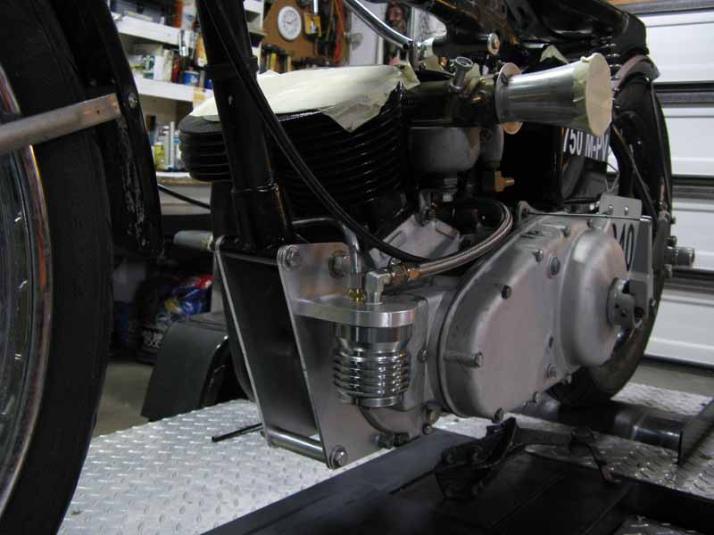
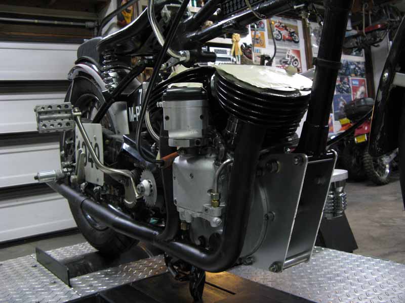
Scouts were notorious for breaking off their front cylinders. I have found that many Scout racers didn't tie the motor's top mount to the frame! I have seen front cylinders break-off on Scouts that I have built, so I decided to get to the bottom of this. I found that the two-piece frame of a Scout has a tremendous amount of twist going on, and the motor's top mount allows the frame to twist the front cylinders off at the base. I came up with a much stronger lower front motor mount to firm things up. First, you use the top mount between the heads, but leave out the bolt to the frame tube. Then, another short cross-tube needs to be welded in near the original generator mount on the frame. This gives another anchor point for the motor mounts. I make up a couple aluminum tubes to go between the new motor plates, and after all the bolts are installed, the front motor mount is a boxed-in section. No more broken cylinders!
Another Important Note for Scout Cylinders
I have seen several Scout cylinders, where someone has cut the deck surface down to try to restore some metal for cutting in a new valve job on cylinders that have had the valve seats cut so much that the valve sinks down in. This is never good. Once a valve is sunk, it loses alot of spring pressure. Plus, you run out of valve adjuster adjustment. There is a way to restore the cylinder geometry by using a new copper "compression plate" under the cylinder base, plus copper rings under the valve guides as well in the same thickness. The stock cylinder height is (on average) 5.807" tall. I have seen them cut down by as moch as .095" down from the deck. This creates all kinds of problems. So, I get Cometic Gaskets to make me custom "Compression Plates", as well as rings for under the valve guides that will raise the cylinder, and restore the proper deck height, and valve cover location (which establishes the proper spring pressures). The pipes, and Intake Manifold will still go on nicely.
The part number for the Compression Plate is: B1431050C (for .050" thick), and MC0249050C for the rings for under the valve guides (for .050" thick). You can ask for other thicknesses.
CONTACT INFORMATION:
James R. Mosher
(505) 466-7870